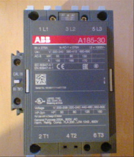
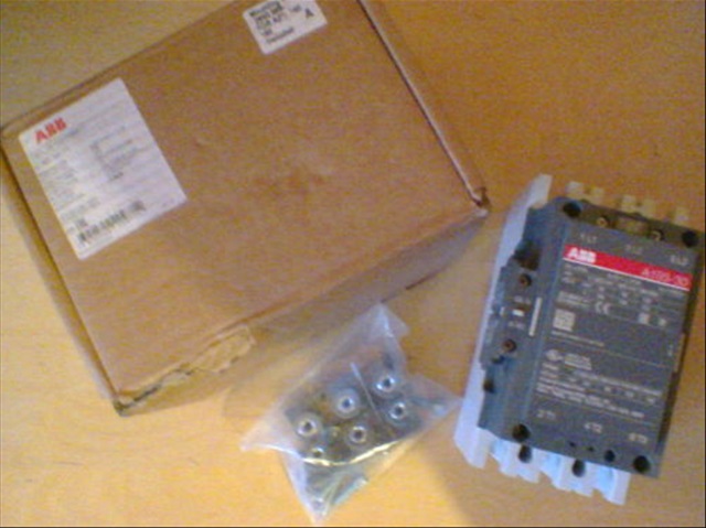
ABB Contactor A185-30-11-88 1SFL491001R8811 supplied with Mounting Kit
SKU:
£280.00
£280.00
per item
A new, un-used item supplied in original packaging - come complete with Mounting Kit (2643-689)
The ABB A185-30-11 1SFL491001R8811 3-phase Contactor suitable for various applications such as Motor starting, Isolation, By-pass and Distribution application up to max 1000 V, 275A
Operated with control voltage, versions from 24….690 AC, 50 and 60 Hz
----------------
Dimensions
•Product Net Depth:160.0 mm
•Product Net Height:196.0 mm
•Product Net Weight:3.500 kg
•Product Net Width:111.5 mm
Container Information
•Package Level 1 Width:170 mm
•Package Level 1 Length:180 mm
•Package Level 1 Height:245 mm
•Package Level 1 Gross Weight:3.5 kg
•Package Level 1 EAN:7320500209714
•Package Level 1 Units:1 piece
Technical
•Number of Main Contacts NC:0
•Number of Auxiliary Contacts NO:1
•Number of Auxiliary Contacts NC:1
•Rated Operational Voltage:Main Circuit 690 V
•Rated Frequency (f):Main Circuit 50/60 Hz
•Conventional Free-air Thermal Current (Ith):acc. to IEC 60947-4-1, Open Contactors q = 40 °C 275 A
•Rated Operational Current AC-1 (Ie):(690 V) 55 °C 250 A
(690 V) 40 °C 275 A
(1000 V) 40 °C 200 A
(1000 V) 55 °C 200 A
(690 V) 70 °C 180 A
(1000 V) 70 °C 180 A
•Rated Operational Current AC-3 (Ie):(1000 V) 55 °C 95 A
(690 V) 55 °C 170 A
(415 V) 55 °C 185 A
(220 / 230 / 240 V) 55 °C 185 A
(440 V) 55 °C 185 A
(380 / 400 V) 55 °C 185 A
(500 V) 55 °C 170 A
•Rated Operational Power AC-3 (Pe):(500 V) 110 kW
(690 V) 132 kW
(220 / 230 / 240 V) 55 kW
(380 / 400 V) 90 kW
(440 V) 90 kW
(415 V) 90 kW
•Rated Breaking Capacity AC-3 acc. to IEC 60947-4-1:8 x Ie AC-3
•Rated Making Capacity AC-3 acc. to IEC 60947-4-1:10 x Ie AC-3
•Short-Circuit Protective Devices:gG Type Fuses 355 A
•Rated Short-time Withstand Current (Icw):at 40 °C Ambient Temp, in Free Air, from a Cold State 30 s 1000 A
at 40 °C Ambient Temp, in Free Air, from a Cold State 10 s 1500 A
at 40 °C Ambient Temp, in Free Air, from a Cold State 15 min 320 A
at 40 °C Ambient Temp, in Free Air, from a Cold State 1 s 2000 A
at 40 °C Ambient Temp, in Free Air, from a Cold State 1 min 800 A
•Maximum Breaking Capacity:cos phi=0.45 (cos phi=0.35 for Ie > 100 A) at 440 V 2000 A
cos phi=0.45 (cos phi=0.35 for Ie > 100 A) at 690 V 1600 A
•Maximum Electrical Switching Frequency:AC-3 300 cycles per hour
AC-1 300 cycles per hour
AC-2 / AC-4 150 cycles per hour
•Rated Operational Current DC-1 (Ie):(110 V) 2 Poles in Series, 40 °C 275 A
(220 V) 3 Poles in Series, 40 °C 275 A
•Rated Operational Current DC-3 (Ie):(110 V) 2 Poles in Series, 40 °C 275 A
(220 V) 3 Poles in Series, 40 °C 275 A
•Rated Operational Current DC-5 (Ie):(110 V) 2 Poles in Series, 40 °C 275 A
(220 V) 3 Poles in Series, 40 °C 275 A
•Rated Insulation Voltage (Ui):acc. to UL/CSA 600 V
acc. to IEC 60947-4-1 and VDE 0110 (Gr. C) 1000 V
•Rated Impulse Withstand Voltage (Uimp):Main Circuit 8 kV
•Mechanical Durability:5 million
•Maximum Mechanical Switching Frequency:3600 cycles per hour
•Coil Operating Limits:(acc. to IEC 60947-4-1) 0.85 x Uc Min. ... 1.1 x Uc Max. (at θ ≤ 70 °C) °C
•Rated Control Circuit Voltage (Uc):60 Hz 240 … 260 V
50 Hz 230 … 240 V
•Coil Consumption:Pull-in at Max. Rated Control Circuit Voltage 60 Hz 600 V·A
Holding at Max. Rated Control Circuit Voltage 50 Hz 35 V·A
Pull-in at Max. Rated Control Circuit Voltage 50 Hz 550 V·A
Holding at Max. Rated Control Circuit Voltage 60 Hz 40 V·A
•Operate Time:Between Coil Energization and NO Contact Closing 13 ... 27 ms
Between Coil De-energization and NO Contact Opening 9 ... 13 ms
Between Coil De-energization and NC Contact Closing 5 ... 10 ms
Between Coil Energization and NC Contact Opening 8 ... 22 ms
•Connecting Capacity Main Circuit:Rigid Al-Cable 25…150 mm²
Bar 24 mm
Rigid Cu-Cable 6…185 mm²
•Connecting Capacity Auxiliary Circuit:Solid 2x1…4 mm²
Flexible with Insulated Ferrule 2x0.75…2.5 mm²
Stranded 2x1…4 mm²
Flexible 2x0.75…2.5 mm²
Flexible with Ferrule 2x0.75…2.5 mm²
•Degree of Protection:acc. to IEC 60529, IEC 60947-1, EN 60529 Coil Terminals IP20
acc. to IEC 60529, IEC 60947-1, EN 60529 Main Terminals IP00
•Connecting terminals (delivered in open position) Main poles:Flat type c/w screws and bolts
•Terminal Type:Main Circuit: Bars
•Number of Main Contacts NO:3
Environmental
•Maximum Operating Altitude Permissible:3000 m
•Resistance to Shock acc. to IEC 60068-2-27:Shock Direction: A 5 g
Shock Direction: C2 5 g
Shock Direction: C1 5 g
Shock Direction: B2 5 g
Shock Direction: B1 5 g
•RoHS Status:Following EU Directive 2002/95/EC August 18, 2005 and amendment
•Ambient Air Temperature:Close to Contactor Fitted with Thermal O/L Relay (0.85 ... 1.1 Uc) -25…+50 °C
Close to Contactor without Thermal O/L Relay (0.85 ... 1.1 Uc) -40…+70 °C
Close to Contactor for Storage -40…+70 °C